Building a Fully Autonomous Industrial Robot From Scratch.
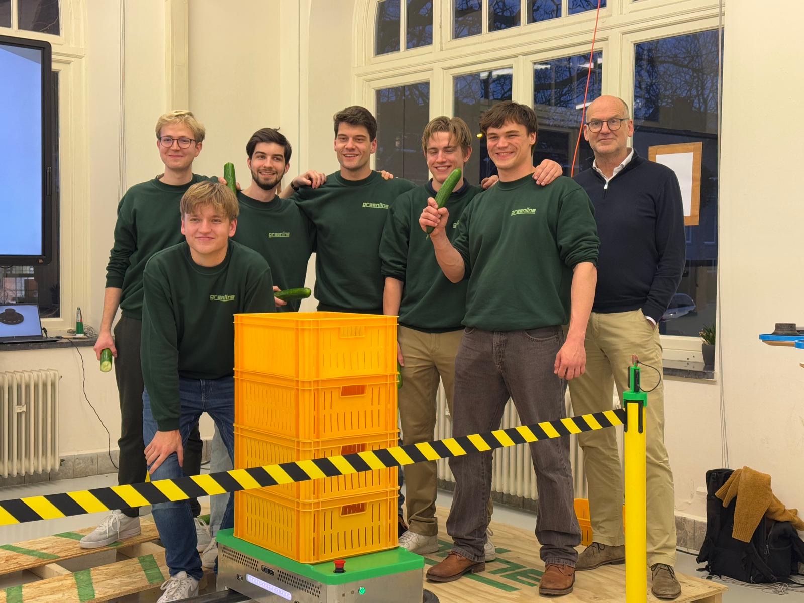
By Vaclav, with teammates Elias Hoste, Huib Maas, Jonas Sjaarda, Twan Vollebregt, and Arthur Oosterman.
Introduction
Over the first semester of my senior undergrad year, my robotics minor group took on a challenge from VDL, a company pioneering greenhouse automation. Their cucumber-harvesting robot can already pick crops autonomously—but moving those crops out of the greenhouse still relies on human labor.
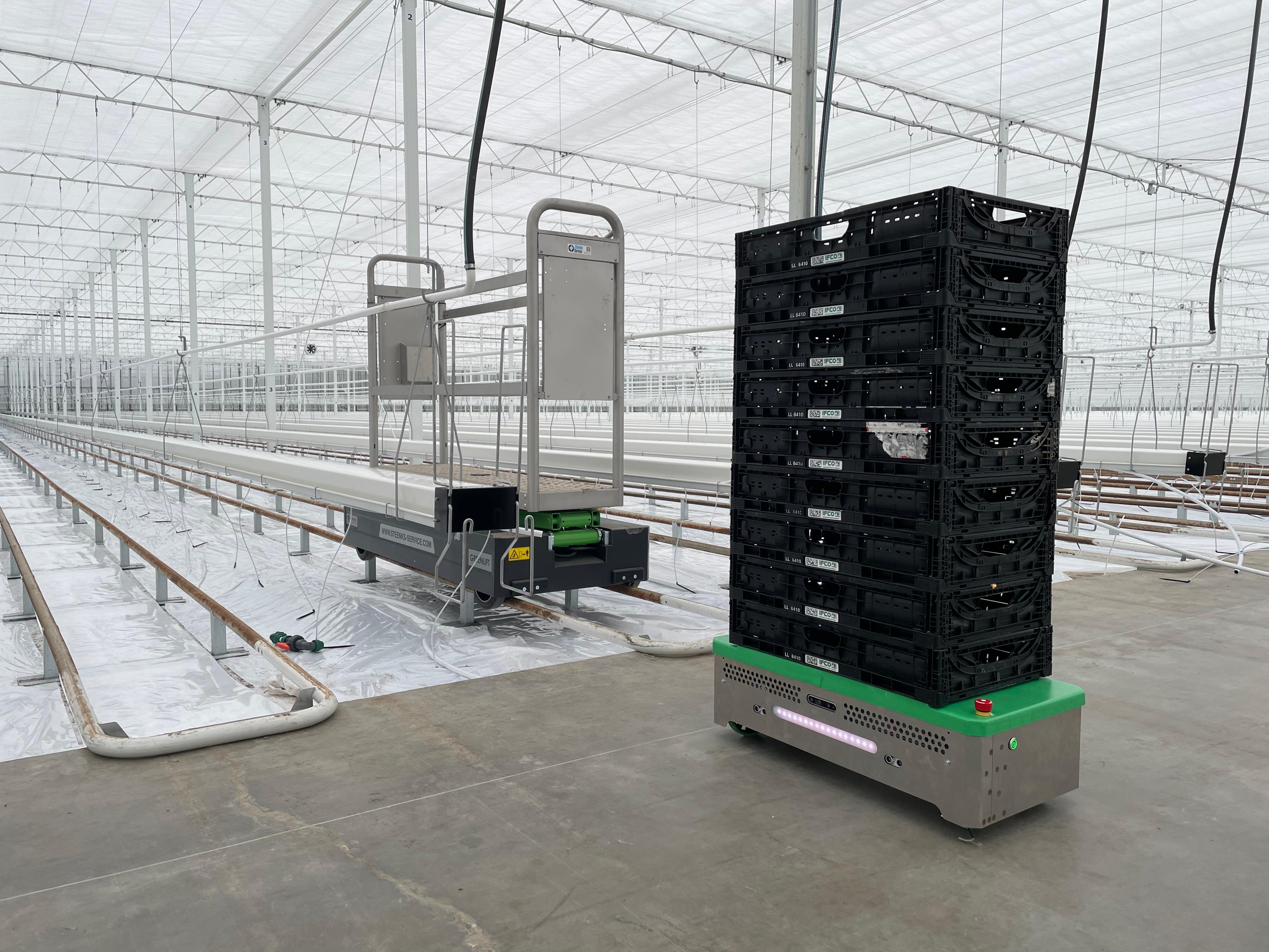
Our assignment: design and build a transportation platform that can collect and carry crates of harvested cucumbers from the harvesting robot to the storage shed where cucumbers are further processed, all while navigating the complex environment of a Dutch greenhouse.
1. The Problem
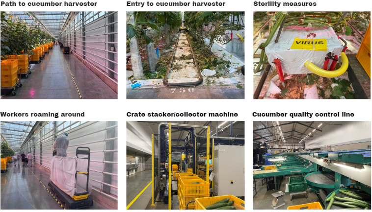
The Netherlands produces over 80% of Europe’s greenhouse vegetables, yet the sector faces a persistent labor shortage. Greenhouses are large, hot, and full of narrow pathways—not the easiest environment for humans or robots.
Currently, crops are transported manually using carts. VDL wanted an automated solution that could:
- Dock with their existing cucumber-harvesting robot.
- Fully autonomously navigate to the cucumber-harvesting robot (no teleoperation required).
- Drive on both concrete and metal rails used between crop rows.
- Operate reliably in hot, reflective, and visually repetitive greenhouse conditions.
- Be safe and never collide with human workers in the greenhouse.
This mix of requirements made the project a genuine multidisciplinary effort.
2. The Robot Design
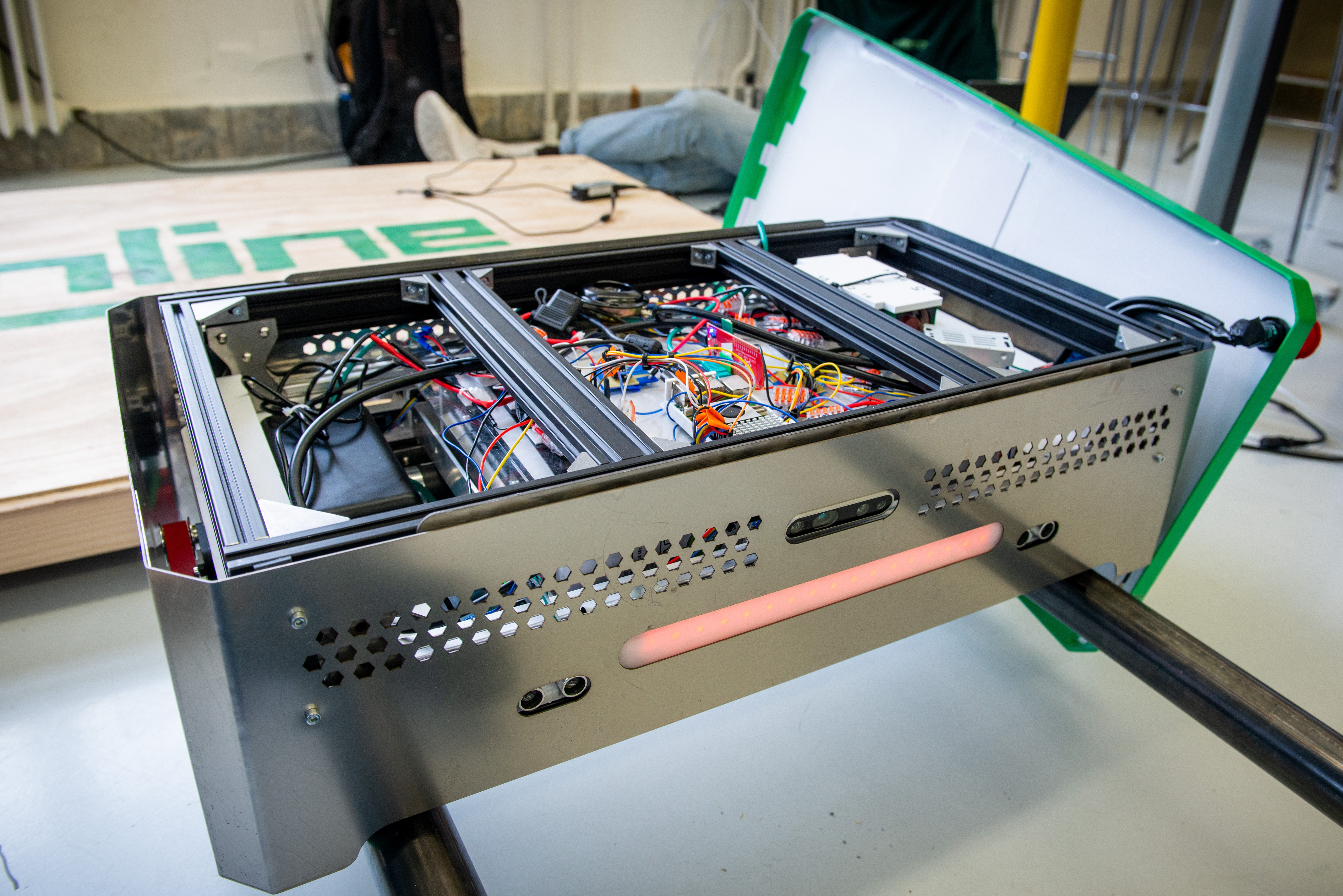
Our mechanical, electrical, and industrial engineering teammates designed and built the physical robot. The frame is made of stainless steel for corrosion resistance and heat endurance, with an active cooling system inside to protect electronics from the high greenhouse temperatures.
A standout feature is the custom 3D-printed concave wheels. Their inner edges ride smoothly on rails, while the outer rims grip concrete paths. This geometry allows the robot to transition seamlessly between surfaces without wobbling or losing traction.
3. Software Architecture
I developed the software stack, which runs on ROS (Robot Operating System). ROS allowed us to structure the robot as a collection of modular, communicating processes—or “nodes”—that handle sensing, navigation, and control independently.
The main components were implemented in Rust for performance and Python for computer vision. All computation runs on a Raspberry Pi 5, chosen for its processing power, connectivity, and compatibility with our sensors and actuators.
3.1 Navigation System
The navigation system operates in three layers:
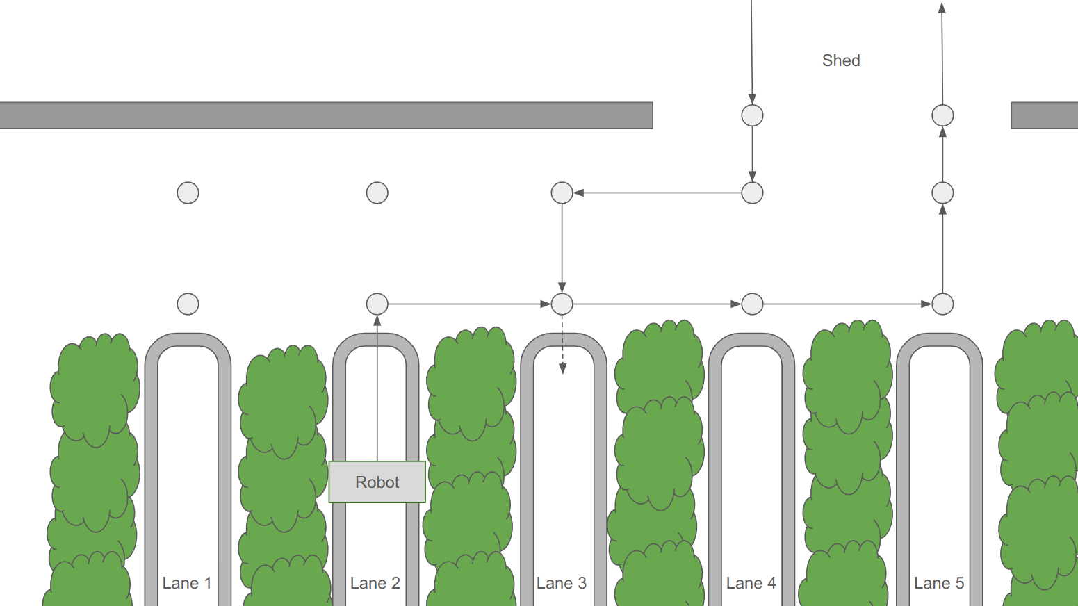
High-level Path Planning
The greenhouse layout is represented as a graph of nodes—key points such as docking areas, rail intersections, and shed entrances. A slightly modified A* algorithm finds the shortest path between nodes using the cost function: \(f(n) = g(n) + h(n) + v(n)\)
where: • g(n) = cost so far, • h(n) = Euclidean distance to target, • v(n) = penalty for excessive turns or congestion.
This approach efficiently guides the robot while avoiding collisions or unnecessary detours.
Mid-level Controller
The mid-level controller interprets the planned path and selects movement strategies using the Strategy Design Pattern. Modes such as path-following, rail alignment, and platooning are defined as independent strategies that can be switched dynamically as the robot moves.
Low-level Differential Drive
At the lowest level, a differential drive controller converts motion commands (linear and angular velocity) into precise wheel speeds via ROS Twist messages, enabling smooth turning and alignment on narrow rails.
Localization
Instead of SLAM—which performed poorly under the greenhouse’s bright lighting and repetitive patterns—we used UWB (Ultra-Wideband) beacon triangulation. This provides centimeter-level accuracy, is simple to deploy, and remains stable even when visual cues are minimal.
3.2 Computer Vision and Rail Alignment
To align accurately with the metal rails, we implemented a custom vision pipeline in Python using OpenCV and the Intel RealSense D435i camera.
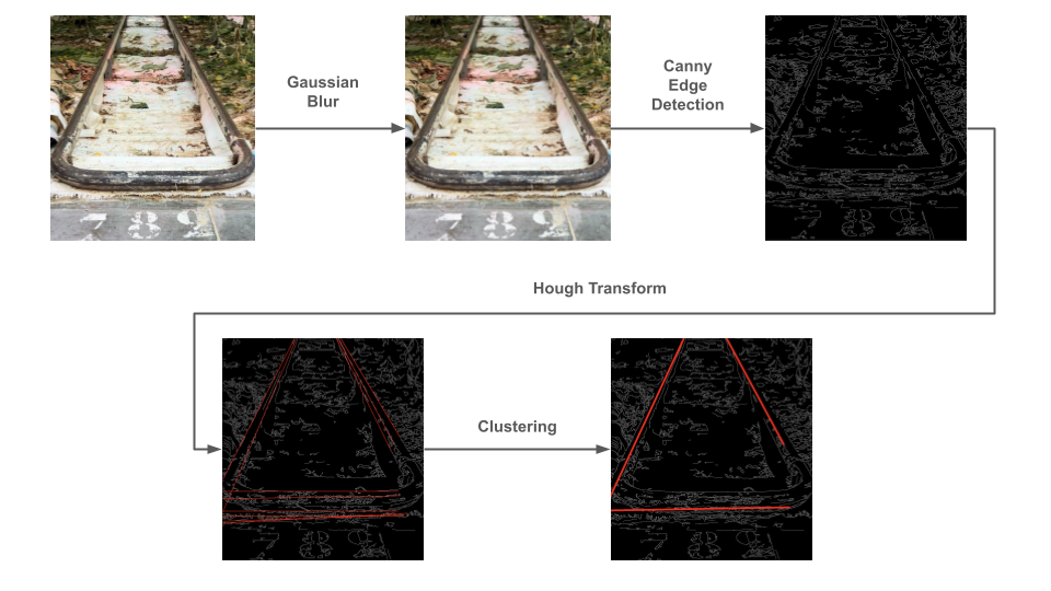
The pipeline performs:
- Image capture from the RealSense camera.
- Gaussian smoothing to remove noise like leaves and shadows.
- Canny edge detection to extract clear line features.
- Hough Transform to detect straight lines corresponding to rails.
- Line clustering by slope and intercept to isolate the two main rails.
- Angle comparison: the robot adjusts until the detected rail angles are symmetric (θ and −θ).
For robustness, line detections are averaged over several frames. This method worked reliably in real greenhouse lighting, outperforming alternative approaches like template matching or depth-based segmentation.
4. Results and Reflections
In the final demonstrations, our robot successfully:
- Navigated both concrete and rails without tilting.
- Docked autonomously with VDL’s harvesting robot.
- Followed planned routes using A* pathfinding.
- Localized robustly via UWB beacons.
- Aligned visually with rails for precise docking.
The project showcased the power of combining mechanical, electrical, and software engineering into one cohesive system. For us, it was a hands-on glimpse into how automation can solve real agricultural problems—and a small step toward the fully autonomous greenhouse of the future.